What are Machinery Cnc Parts, and how do manufacturers make them? These questions reach far beyond cutting metal into attractive shapes. CNC parts are engineered components produced by computer-controlled machines, including mills, lathes, routers, and grinders. They support medical devices, aircraft systems, industrial equipment, and everyday products.
Dr. Mikell P. Groover, a respected manufacturing engineering author, describes CNC as “a form of programmable automation.” That idea explains the process clearly. An engineer creates a digital model, then converts its dimensions into machine instructions. The machine removes material from aluminum, steel, brass, titanium, or engineering plastics. A cutting tool moves across the workpiece with controlled speed and measured force. Coolant may flow over the tool. Chips collect beside the vise.
Accuracy begins before machining starts. Designers must consider tolerances, tool access, surface finish, and material behavior. Operators then secure the stock, check the program, and measure the finished part. A coordinate measuring machine may verify a hole position within a few microns. Small errors matter. One incorrect datum can affect an entire assembly.
The process is powerful, but it is not automatically perfect. A flawless CAD model cannot fix poor material selection or careless inspection. Even experienced manufacturers review tool wear, vibration, and temperature changes. This article examines each production stage, from digital design to final quality control, while showing where practical judgment still matters. Understanding these details makes Machinery Cnc Parts easier to evaluate, specify, and improve.
CNC machinery parts are precision components controlled by computer numerical code. They include spindles, guide rails, ball screws, tool holders, fixtures, housings, and cutting tools. Each part supports movement, cutting accuracy, or structural stability. Their role is practical: they convert programmed instructions into repeatable physical actions.
A spindle transfers rotational force to the cutting tool. Guide rails control linear movement, while ball screws reduce friction and positioning errors. Fixtures hold raw material firmly during machining. Even a small alignment problem can create visible defects on a metal surface. According to Grand View Research’s 2024 market analysis, the global CNC machine market was valued at approximately USD 86 billion in 2023. This growth reflects rising demand for accurate, automated production across aerospace, medical, automotive, and general engineering sectors.
Manufacturers usually make these parts from hardened steel, cast iron, aluminum, or engineered polymers. The process may include turning, milling, grinding, heat treatment, and surface coating. Quality teams inspect dimensions with coordinate measuring machines and calibrated gauges. ISO 230-2 testing guidance is commonly used to evaluate machine positioning accuracy. Still, accuracy is not automatic. A carefully machined part may fail if lubrication is poor or assembly tolerances are misunderstood. That is where practical experience matters. The drawing is only the beginning.
CNC machinery parts include shafts, gears, housings, brackets, flanges, and precision fixtures. Each part begins with a CAD model and a material choice. Turning produces round shafts and bushings. Milling creates pockets, slots, and complex surfaces. Drilling forms accurate holes, while grinding improves final tolerances. Operators then inspect dimensions using calipers, micrometers, or coordinate measuring machines.
Aluminum alloys, especially 6061 and 7075 are common because they combine low weight with good machinability. Stainless steel suits corrosive environments and food-processing equipment. Carbon steel offers strength at a lower cost, but it needs surface protection. Tool steel supports dies and cutting components under repeated loads. Brass works well for fittings and electrical contacts. Titanium performs strongly in demanding applications, though machining it requires careful heat control. Engineering plastics can reduce friction and electrical conductivity.
Material selection has measurable environmental consequences. The International Aluminium Institute reports that recycled aluminum uses about 5% of the energy required for primary aluminum production. The World Steel Association estimates steelmaking causes roughly 7–9% of global carbon dioxide emissions. These figures should influence design decisions, not merely marketing language. A lighter part may reduce operating energy, yet excessive machining can create unnecessary scrap. In practice, the “best” material is rarely universal. Engineers must balance tolerance, load, corrosion, cost, and repairability. Small design errors still become expensive chips.
CNC machinery parts begin with a precise digital definition, not a cutting tool. Engineers create a 3D CAD model with datums, tolerances, hole positions, and surface-finish requirements. A shaft may look simple, yet a few microns of misalignment can cause vibration or premature wear. Material behavior matters too. Aluminum cuts differently from hardened steel.
The CAD model then enters CAM software, where engineers select tools, cutting paths, spindle speeds, and feed rates. The software converts these decisions into machine instructions, commonly G-code. A postprocessor adapts the code to a machine’s controller. This step is easy to underestimate. The same toolpath can behave differently after a machine’s axis limits or coordinate system changes. Simulation checks collisions, excess material, and tool access before production. Still, simulation is not reality. It may miss tool deflection, heat, or an incorrectly measured work offset.
Deloitte’s 2023 Smart Manufacturing and Operations Survey reported that 86% of manufacturers viewed smart manufacturing as important for competitiveness within five years. That pressure encourages connected design, automated inspection, and program traceability. In practice, programmers often verify the first part with probing, gauges, and measured inspection data. ISO GPS standards help communicate geometric requirements consistently. However, drawings can remain unclear when designers overuse tight tolerances. That raises machining time and cost without improving function. A better program balances accuracy, tool life, cycle time, and the part’s actual purpose. Small errors still teach the most.
| CNC Part or Feature | Typical Function | Common Materials | Typical Manufacturing Process | Typical Dimensional Tolerance | Typical Surface Finish | Design and Programming Considerations |
|---|---|---|---|---|---|---|
| Machine Base or Frame | Supports the machine structure and absorbs cutting forces and vibration. | Cast iron, fabricated steel, mineral casting, or structural aluminum. | Fabrication or casting followed by CNC milling, drilling, grinding, and stress relief. | Commonly ±0.05 to ±0.20 mm, depending on size and function. | Approximately Ra 1.6–6.3 µm on machined mounting surfaces. | Designers provide flat reference surfaces, mounting points, access for tools, and adequate rigidity. Programs often use face milling, pocketing, drilling, and probing cycles. |
| Spindle Housing | Holds and aligns the spindle assembly while maintaining rotational accuracy. | Cast iron, alloy steel, or high-strength aluminum. | CNC milling, boring, reaming, heat treatment when required, and precision grinding. | Commonly ±0.01 to ±0.05 mm for bearing seats and alignment features. | Approximately Ra 0.4–1.6 µm on bearing and locating surfaces. | Critical bores require controlled datum structures, coaxiality, and thermal considerations. CNC programs may use finish boring, reaming, probing, and multiple setup alignments. |
| Spindle Shaft | Transfers rotary motion and cutting torque to the tool or workholding device. | Hardened alloy steel, tool steel, or stainless steel. | Turning, heat treatment, cylindrical grinding, spline machining, and balancing. | Commonly ±0.005 to ±0.02 mm on critical diameters. | Approximately Ra 0.2–0.8 µm on bearing journals and locating tapers. | Design requires concentricity, balance, hardness, and precise bearing fits. Toolpaths must control cutting forces and avoid distortion during finishing. |
| Linear Guide Rail | Guides the movement of machine axes with low friction and high repeatability. | Hardened alloy steel with precision-ground contact surfaces. | Heat treatment, precision grinding, surface finishing, and inspection. | Often controlled within ±0.01 to ±0.03 mm over a defined reference length. | Approximately Ra 0.2–0.8 µm on functional guide surfaces. | Designers specify straightness, parallelism, mounting-hole position, and preload requirements. CNC drilling and tapping programs must reference accurate datums. |
| Ball Screw | Converts motor rotation into accurate linear axis movement. | Hardened alloy steel, precision-ground steel, and bearing steel. | Thread forming or grinding, heat treatment, precision finishing, and preload assembly. | Positioning accuracy varies by grade; commonly specified in micrometers per 300 mm. | Approximately Ra 0.2–0.8 µm on raceway surfaces. | Design includes lead accuracy, preload, critical speed, support bearings, lubrication, and thermal expansion. Programming compensates for backlash, pitch error, and machine-axis limits. |
| Worktable or Machine Bed | Provides a stable surface for fixtures, vises, workpieces, and coordinate references. | Cast iron, steel, or aluminum alloy. | CNC face milling, slotting, drilling, tapping, grinding, and surface treatment. | Commonly ±0.03 to ±0.10 mm for mounting and reference features. | Approximately Ra 1.6–6.3 µm on general machined areas. | Design must account for clamping loads, chip evacuation, T-slots or threaded holes, and accessibility. Programs use facing, pocketing, drilling, and tapping operations. |
| Fixture Plate or Soft Jaw | Locates and securely holds a workpiece during machining. | Aluminum, mild steel, alloy steel, or engineering plastic for non-marring contact. | CNC milling, drilling, tapping, contouring, and jaw profiling. | Commonly ±0.02 to ±0.10 mm, depending on locating requirements. | Approximately Ra 1.6–3.2 µm on locating surfaces. | Design follows the 3-2-1 locating principle, avoids part distortion, and allows tool and chip access. Programs use datum probing, pocketing, drilling, and contour finishing. |
| Tool Holder or Collet Nut | Secures the cutting tool and transfers torque from the spindle. | Hardened alloy steel, tool steel, or spring steel. | Turning, milling, grinding, heat treatment, thread machining, and balancing. | Commonly ±0.005 to ±0.02 mm on tool-location features. | Approximately Ra 0.2–0.8 µm on taper and bore surfaces. | Design focuses on runout, balance, gripping force, taper geometry, and tool reach. Programming should use appropriate tool-length and diameter offsets. |
| Cutting Tool | Removes material from the workpiece through controlled cutting motion. | Carbide, high-speed steel, ceramic, cubic boron nitride, or diamond-coated material. | Grinding, edge preparation, coating, and dimensional inspection. | Tool geometry is commonly controlled to a few micrometers for precision applications. | Cutting-edge and flute finishes depend on tool type and application. | Tool selection considers workpiece material, rigidity, depth of cut, chip load, spindle speed, coolant, and tool life. CAM software calculates feeds, speeds, stepovers, and toolpaths. |
| Precision Bushing or Bearing Seat | Supports rotating components and maintains alignment between moving parts. | Bearing steel, hardened alloy steel, bronze, or engineered polymers. | Turning, boring, reaming, honing, grinding, and heat treatment when required. | Commonly ±0.005 to ±0.02 mm for controlled fits. | Approximately Ra 0.2–0.8 µm on functional bores and journals. | Designers specify fit class, roundness, cylindricity, and surface hardness. Finishing operations should use stable workholding and controlled tool wear compensation. |
| Coolant Nozzle | Directs cutting fluid toward the tool, cutting zone, or workpiece. | Stainless steel, brass, aluminum, or chemical-resistant polymer. | CNC turning, milling, drilling, bending, brazing, or additive manufacturing. | Commonly ±0.05 to ±0.20 mm, depending on the nozzle and mounting design. | Approximately Ra 1.6–6.3 µm on machined surfaces. | Design considers flow rate, pressure, adjustment range, chip clearance, and heat resistance. Programs must avoid thin-wall distortion and maintain clear internal passages. |
| Control Panel Enclosure | Protects electrical and control components from impact, dust, and coolant. | Powder-coated steel, stainless steel, or aluminum sheet. | Laser cutting, CNC punching, press braking, milling, welding, and coating. | Commonly ±0.10 to ±0.50 mm for sheet-metal features. | Brushed, painted, anodized, or powder-coated surfaces. | Design includes bend allowances, cable access, ventilation, sealing, grounding, and service access. CNC programs use nesting, drilling, bending sequences, and edge-finishing operations. |
| CNC-Machined Workpiece | Final component produced by removing material according to a digital design. | Aluminum alloys, steels, stainless steels, brass, titanium, plastics, or composites. | Turning, milling, drilling, boring, tapping, grinding, and secondary finishing. | General features may be ±0.05 mm; precision features may require ±0.005 to ±0.02 mm. | Typical machined surfaces range from Ra 0.8–6.3 µm; polishing or grinding can produce finer finishes. | The workflow normally includes CAD modeling, design-for-manufacturing review, CAM toolpath creation, post-processing into G-code, simulation, setup, machining, and inspection. |
| Note: Tolerance and surface-finish values are typical planning ranges rather than universal limits. Actual results depend on machine condition, material, tooling, workholding, thermal stability, tool wear, inspection method, and the specified engineering drawing. | ||||||
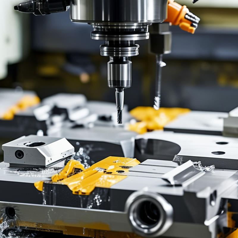
CNC machinery parts begin as digital models created from precise engineering drawings. The model defines holes, slots, threads, curves, and required tolerances. A machinist then selects suitable stock, such as aluminum, steel, brass, or engineering plastic. Material choice affects cutting speed, tool wear, and final strength.
The process begins by importing the model into manufacturing software. Programmers create toolpaths for drilling, milling, turning, or facing. Simulation can reveal collisions and excessive cutting loads before production starts. The operator secures the material firmly and sets the machine’s work origin. Cutting tools are measured carefully, then installed in the correct sequence. The machine removes material in several controlled passes. Roughing removes most waste, while finishing creates smoother surfaces. Coolant may reduce heat and protect the cutting edge. After machining, the part is deburred, cleaned, and inspected with gauges or a coordinate measuring system. Small errors can still occur. A second inspection is often worthwhile.
Tips: Keep workholding rigid and confirm the zero point twice. Use sharp tools for cleaner edges. Record tool offsets and inspection results. Do not trust simulation alone; real material can behave differently. Leave extra stock for finishing when tight tolerances matter. A practical review after each batch can reveal vibration, heat marks, or unexpected tool wear before they affect more parts.
CNC machinery parts leave the machine only after more than a visual check. In a typical workshop, inspectors compare each part with the approved drawing and tolerance notes. Calibrated micrometers measure shafts, bores, and wall thicknesses. Coordinate measuring machines verify complex profiles and hole positions. Surface roughness testers reveal marks that fingers may miss. Every reading should be traceable to a calibrated instrument and a recorded inspection plan.
Quality control also includes material checks, tool monitoring, and sample testing during production. Operators watch for burrs, chatter marks, heat discoloration, and gradual tool wear. A part can meet its dimensions yet fail during assembly. That is why fit tests and functional checks matter. Inspection records should identify the batch, machine, operator, and measured values. Small omissions happen. They deserve correction, not concealment.
Finishing changes both performance and appearance. Deburring protects technicians and prevents damage to mating components. Grinding, polishing, plating, anodizing, or protective coating may improve wear resistance and corrosion protection. The selected finish must match the part’s material and working environment. Final applications include robotic joints, pumps, medical equipment, transport systems, and precision fixtures. Each use demands different priorities, such as low friction, tight sealing, or clean surfaces. In practice, finish thickness can be overlooked near edges and internal corners. A second inspection there is often worthwhile.
Same Day Shipping
ISO Certified Production